Resets in FPGA Design
January 2011
When I was an ASIC designer, it was drummed into me that you always reset your logic design. Of course, what was meant was that a digital system should always power-up in a known state, and a reset controller would ensure that each and every module on-chip would see assertion of a hard reset, or power-on reset (POR). The idea behind reset is much more than aesthetics; it's about repeatability, particularly as it relates to verification of a design. If a set of circumstances, a stimulus, causes a fault, then recreation of the same circumstances should recreate the fault—the first step towards a successful bugfix.
It wasn't always this way, and nowadays we may have returned to those old days in the modern FPGA era, where reset has become a dirty word. The old argument, that reset was costly to get right and resource hungry, has made a resurgence in modern FPGA design practice. Good examples of this thinking can be found in recent Xilinx recommendations, Get Smart About Reset: Think Local, Not Global, and Get your Priorities Right—Make your Design Up to 50% Smaller. These take the view that not only are resets unnecessary, but they can actually degrade your synthesis quality of results. In this article, we'll look at living in a "low reset" world, and explore design practices that map well to FPGAs.
The Problem with FPGA Resets
The global-reach H-tree nets found in ASIC designs are often not available for reset use in FPGAs. In this respect, Altera have provided better options with their Stratix global nets, but Xilinx have not offered global distribution of anything other than clocks up until their Virtex-5 family of FPGAs. As a result, designers have been forced to distribute resets, and other high-fanout signals, via normal fabric routing networks, which impose significant levels of delay and skew for large fanouts. Both delay and skew give rise to some unfortunate side effects in a system, regardless of whether resets are synchronous or asynchronous:
- Resets that negate in different clock cycles across a design mean that some flip-flops come out of reset ahead of others, and this can (and probably will) lead to improper start-up behaviour due to illegal states.
- Resets that negate within the setup and hold critical window of flip-flops (that is, violate the flip-flop's recovery and removal specifications) are as detrimental to their operation as any other metastability.
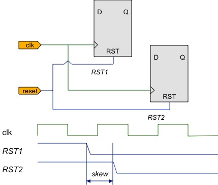
Two flip-flops being released from reset in different clock cycles due to reset skew.
The ideal, then, is to route reset signals such that they all negate at destination logic within a single clock cycle. Unfortunately, this is easier said than done as clock frequencies increase and devices scale up to the point where it takes more than one cycle to propagate any signal across the die. What worked at 50MHz isn't going to scale too well to 200MHz. Having been personally bitten by reset issues, such as flip-flops releasing in different cycles, I can attest to how extremely time consuming these issues are to debug, so they're best avoided in the first place.
The other concern with hand-crafting reset nets is their cost in terms of both logic resources and degradation of operating frequency (Fmax). This stems mainly from resets competing with functional logc for the same resources. For instance, Fmax may be reduced whenever resets cannot be directly absorbed into logic elements, and this can introduce extra logic on critical paths. Similarly, the burden of placing and routing reset nets degrades the placement and routing of system logic. However, it is also easy to overstate the resource cost of resets, which may be only in the order of a few percent.
It is also worth carefully reading the FPGA vendor's datasheets and HDL guides, as they define the kinds of resets supported in various clocked logic. Frequently, advanced hard macros, such as DSP blocks, FIFOs, and SERDES, may support only limited reset options, or none at all. Resetting such logic incorrectly can therefore prevent inference of specialised macros, and badly affect performance as regular LUT logic is inferred in its place.
Why Reset?
At the outset we should realise that soft-programmable FPGAs are inherently initialised
whenever the design bitstream is loaded into the device from its boot EEPROM.
As such, every flip-flop in your design will almost certainly be given a default value.
However, while this addresses the behaviour of the silicon, it doesn't cleanly initialise
your simulations, which would quickly become a sea of undefined red.
One approach to ensuring silicon-simulation coherence is to explicitly initialise your
register signals in the RTL code.
For example, the following VHDL ensures that your q_dout register is
reset to zero in both the FPGA load and in simulation:
architecture cleared_regs_rtl of cleared_regs is
   -- declare initialised register
   signal q_dout   : std_logic_vector(7 downto 0) := (others => '0');
begin

   registers : process (clk) is
   begin
      -- no hard reset required!
      if rising_edge(clk) then
         q_dout    <= din;
      end if;
   end process registers;

end architecture cleared_regs_rtl;
In many cases, this kind of initialisation is all that it takes. But the fundamental problem with this approach is that it requires the entire FPGA to be rebooted in order to effect reset. If your design is deployed in a robust, high-availability situation, you may not have the luxury or even the physical means to reboot the device and wait hundreds of milliseconds for configuration to complete. Your FPGA will, in this case, only go through a reboot cycle on power-up.
There are arguably many legitimate reasons for constructing resets apart from device reboot in real-world designs. Some likely scenarios include:
- Your clock source drops out, and the design has to reset upon reacquiring PLL lock.
- A communication link partner loses sync, and the channel must be reset.
- A user-accessible push button or microprocessor is permitted to reset most of the system, following, say, expiry of a watch dog timer.
- You use partial reconfiguration in modern FPGAs and the swapped logic block must be reset independently of its environment.
- The design adopts legacy IP from an ASIC or an IP vendor, and it requires reset just as it does when used outside of FPGAs.
- The design supports a standby or disabled state that appears for all intents and purposes to be a reset.
Note that in none of these scenarios did we apply reset just to make simulations clean. But the effect of having the reset still means that we must simulate reset behaviour, and support it in the functional design. That FPGA vendors do not support such cases well shows that they have dropped the ball in consulting with their customers and supporting fundamental usage.
Synchronous and Asynchronous Reset
A perennial argument in reset discussion is whether to adopt asynchronous or synchronous reset assertion styles. Almost like fashion, the prevailing trend has swung back from asynchronous to a clear preference for synchronous resets in larger, more modern FPGAs. In truth, there's a good place for both styles of resets. In particular, while I would happily apply synchronous resets to the bulk of my application logic, I would continue to use asynchronous resets in limited cases to initialise top-sheet logic, such as PLLs and the main reset controller itself.
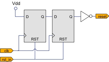
Conditioning an asynchronous reset, rst_in, to negate synchronously with respect to clk on output reset.
Asynchronous resets are necessary where no guarantee of stable clocks can be made—hence the use around PLLs. If asynchronous resets are needed elsewhere in order to force a design to reset, then it's more than likely that the design is broken by race conditions and feedback loops. The two main reasons to favour synchronous resets are that asynchronous resets tend to be improperly implemented, and synchronous reset signals can be readily absorbed into the logic cones of functional logic.
The most frequent mis-application of asynchronous resets is to think of them as asynchronous on all edges. Rather, the only time the reset can be considered asynchronous is upon its assertion. The signal must negate synchronously, and within a single clock cycle, or the dreaded partial release, recovery, and removal violations will wreak havoc. The figure shows one of the simplest reset conditioning circuits for taking a truly asynchronous reset signal and ensuring that the output negates synchronously, even though it may assert asynchronously. The double (or triple) registers minimise the probability of metastability for inopportune changes to the incoming reset. One such conditioning circuit is required for every distinct (unrelated) clock domain being asynchronously reset. Clearly, using asynchronous resets does not permit blissful ignorance of timing concerns.
Needless to say, a synchronous reset generator also needs a conditioning circuit, but followed by a double-registered synchroniser to make both assertion and negation synchronous with respect to clock edges.
The benefit of using the best natively supported reset style is not to be underestimated. For example, on a Virtex-6 FPGA synchronous sets and resets asserted active-high are supported directly by the fabric routing, and yield the most efficient reset option. I have seen up to 50MHz speed improvements in Virtex-6 designs that were migrated from asynchronous active-low resets to the preferred, synchronous active-high strategy. A significant part of the improvement in synchronous reset comes from synthesis optimisations that use flip-flop reset pins to clear registers whenever functional signals would otherwise assign zero to a register. Again, studying the vendor's datasheets and HDL guides pays off.
Minimising Resets
Unlike the FPGA vendors, who assume a simple reboot on reset, we have to actually implement our reset / clear / enable from the available resources at hand. However, given that we face significant timing closure issues on high fanout nets routed through the fabric, it makes sense to head off problems with as few reset registers as possible.
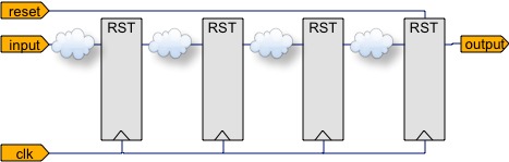
Partially reset pipeline avoids a reset to each stage.
The golden rule in minimal reset design is: all registers that receive state through feedback must be reset. A classic example of such registers are the state of a finite state machine. But equally important, any register that is not guaranteed update on every clock cycle—such as conditionally updated hold registers—are also likely to fall into the feedback category. However, registers that are naturally updated from inputs, or pipelines that flush themselves from neighbouring inputs do not need reset. As a compromise, reset the output stages of pipelines, as the figure shows, and ensure that reset is always asserted long enough to properly flush every pipestage. In simulation this ensures that all stages eventually assume valid values, and by resetting module outputs we can rapidly reset all pipelines in parallel.
Since many modules naturally enter a start-up state whenever a controlling state machine or enable is in reset, it makes sense to just reset the state machine, and let it initialise the remaining logic. Sometimes adding reset as an inclusive-OR term for such states is enough to reset large portions of the control logic, while the datapath logic can be flushed as described earlier. The beauty of this approach is that our reset has become a local problem, without unnecessarily loading the reset net.
While such approaches work fine, they leave me apprehensive as to whether I have
successfully put my entire design into reset when required.
After all, it's easy enough to miss just one feedback register case.
Given adequate reset routing, you could simply reset all registers and guarantee
correct behaviour—another argument for FPGA vendors to support this properly.
However, for now it will be necessary to carefully simulate reset scenarios.
I would start by understanding the worst-case reset time (say, to flush long pipelines),
and define a minimum reset hold requirement.
Starting with registers undefined (as at the beginning of a RTL simulation),
assert reset for this minimum period, and verify that all registers in your design
have their valid reset values at the point reset negates.
It helps to name all register signals in a fashion that quickly identifies them as
registers, such as prefixed with q_ or suffixed _reg, in order
to dump them in simulation.
Alternative Reset Routes
As designs grow in size, the load on heavily fanned-out nets, such as resets, will inevitably prohibit reasonable operating frequencies without alternative routing strategies. Some of the options to be considered include:
- Using a dedicated global route normally used for clocks (such as a BUFG in Xilinx Virtex-5 and Virtex-6) to convey signals across the fabric. Even where this is not physically restricted by the FPGA architecture or vendor tools, the delay on such routing can be several nanoseconds once entry into the fabric has been accounted for.
- Using timing constraints to force the reset net to a multi-cycle path, with minimum and maximum delays. The idea here is to set the minimum delay to greater than one clock period so as to match the worst-case arrival time. This can be difficult to set-up, and may consume many buffer elements to delay early-arriving copies of the signal. It also makes constraints dependent on the clock periods being used elsewhere in the design.
- Break the reset timing arc by a hierarchy of pipeline registers. At each level of hierarchy, the reset is fanned out from cloned copies of a pipeline register, thus minimising the load on individual reset nets, and allowing reset to take several clock cycles to propagate from source to the furthest flip-flops.
The pipelined reset distribution strategy works well in practice, although it takes some manual effort to create a reset repeater block, and instantiate it at varying levels of the design hierarchy. It becomes a matter of practice to include a reset repeater at the top-sheet module of every large subsystem in your design. Use of synthesis maximum fanout constraints can even assist with automatic cloning of the repeater registers in some tool flows. Take care, however, that pipelined resets don't reach their destination flip-flops in different clock cycles unless these belong to different modules, which can tolerate release from reset at different times.
Recommendations
The single most important consideration for the future is that the distribution of resets—and other high fanout signals—must be planned for from day one. Such planning will involve design practices to localise resets, minimise register reset to feedback elements, and inclusion of reset repeater blocks.
Specific implementation of resets must be closely tied to vendor's native support. Hence, issues such synchronous versus asynchronous, and active high or low should be decided on the basis of datasheets, and configurable logic capabilities. However, I would expect to see increasing use of synchronous, active high resets in modern designs.
I would hope that FPGA manufacturers treat resets with a little less flippancy than they have in the past, and actively work with their customers on more flexible support. As an example of where this could head, I would suggest provision of general-purpose, low-skew routing networks, terminated by dedicated registers and serving small groups of configurable logic cells. Such networks would allow synchronous distribution of signals over more than a clock cycle to most of a large design.